Assembly
How it goes together.
Two widths, two kits each, a sheet apiece. Every count on this page is the bill the box is priced from, and every picture is drawn from the parts you will print: the step’s parts dark, what is already in place light. Print the one for your rack and keep it on the bench.
The 3U base kit
16 printed parts, 44 bolts, 5 steps.
You need
- 5 mm hex key, for the M6 screws
- 4 mm hex key, for the M5 screws
- 10 mm and 8 mm spanners, for the nuts
In the box
| 4 | Post |
|---|---|
| 2 | Bottom bar |
| 2 | Top bar |
| 2 | Side rail |
| 1 | Base tile, front left |
| 1 | Base tile, front right |
| 1 | Base tile, back left |
| 1 | Base tile, back right |
| 2 | Top rail, handle |
| 36 | M6 heat-set insert, 8 mm |
| 40 | M6 nyloc nut (DIN 985) |
| 40 | M6 x 16 socket screw |
| 4 | M5 x 20 socket screw |
| 4 | M5 nyloc nut (DIN 985) |
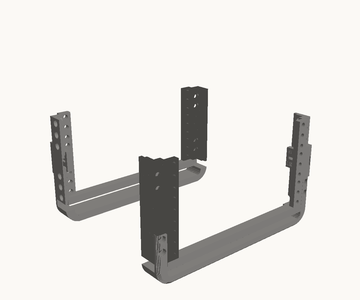
Step 1: Bolt a bottom bar across each pair of posts
- 2
- Bottom bar
- 4
- Post
- 8
- M6 x 16 socket screw
- 8
- M6 nyloc nut (DIN 985)
Stand two posts up with their mounting faces towards you and their side plates outward, and drop a bottom bar’s ears into the pockets at their feet, spine down: the ears sit in the pockets flush with the faces. Two M6 × 16 through each ear from the front, into a nut behind the post’s mounting plate. Make the second pair the same way; it becomes the back, turned round.
Check. Two U-frames. Ears flush with the faces, nothing standing proud, and the side plates on the outside of each.
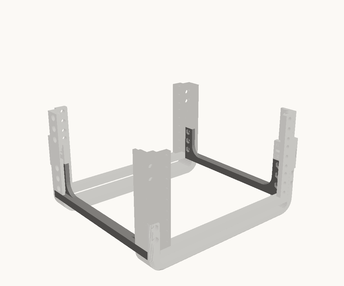
Step 2: Join the two with the side rails
- 2
- Side rail
- 12
- M6 x 16 socket screw
- 12
- M6 nyloc nut (DIN 985)
A side rail runs between a front post and a back post: its flange turned outward under the posts’ feet, and the bolt plate at each of its ends standing inside the post’s side plate. Drop a nut into each of the three traps in the plate from inside the rack, then three M6 × 16 through the side plate from outside, into them. The other rail the same on the other side.
Check. The rack stands square on its bars and rails. Each rail’s plate is inside the post’s side plate, not outside it, and three bolt heads show on the outside of every post’s foot.
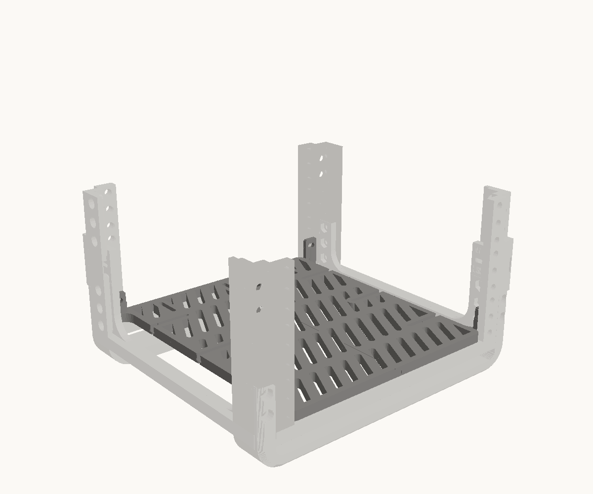
Step 3: Lay the base in and bolt it up into the posts
- 1
- Base tile, front left
- 1
- Base tile, front right
- 1
- Base tile, back left
- 1
- Base tile, back right
- 4
- M5 x 20 socket screw
- 4
- M5 nyloc nut (DIN 985)
Four tiles, each with a prong at its outer corner, meeting in the middle where their edges lap. Each prong goes up inside a post behind its mounting plate; the front pair sit flat against the plate. Line the slot in each prong up with the post’s second mounting hole from the bottom and put an M5 × 20 through from the face, into a nut on the far side of the fin.
Check. All four tiles flat with their laps closed, the base on the same plane as the rack’s feet, 3 mm back from the front faces. A rack ordered with an open bottom has no tiles: skip this step.
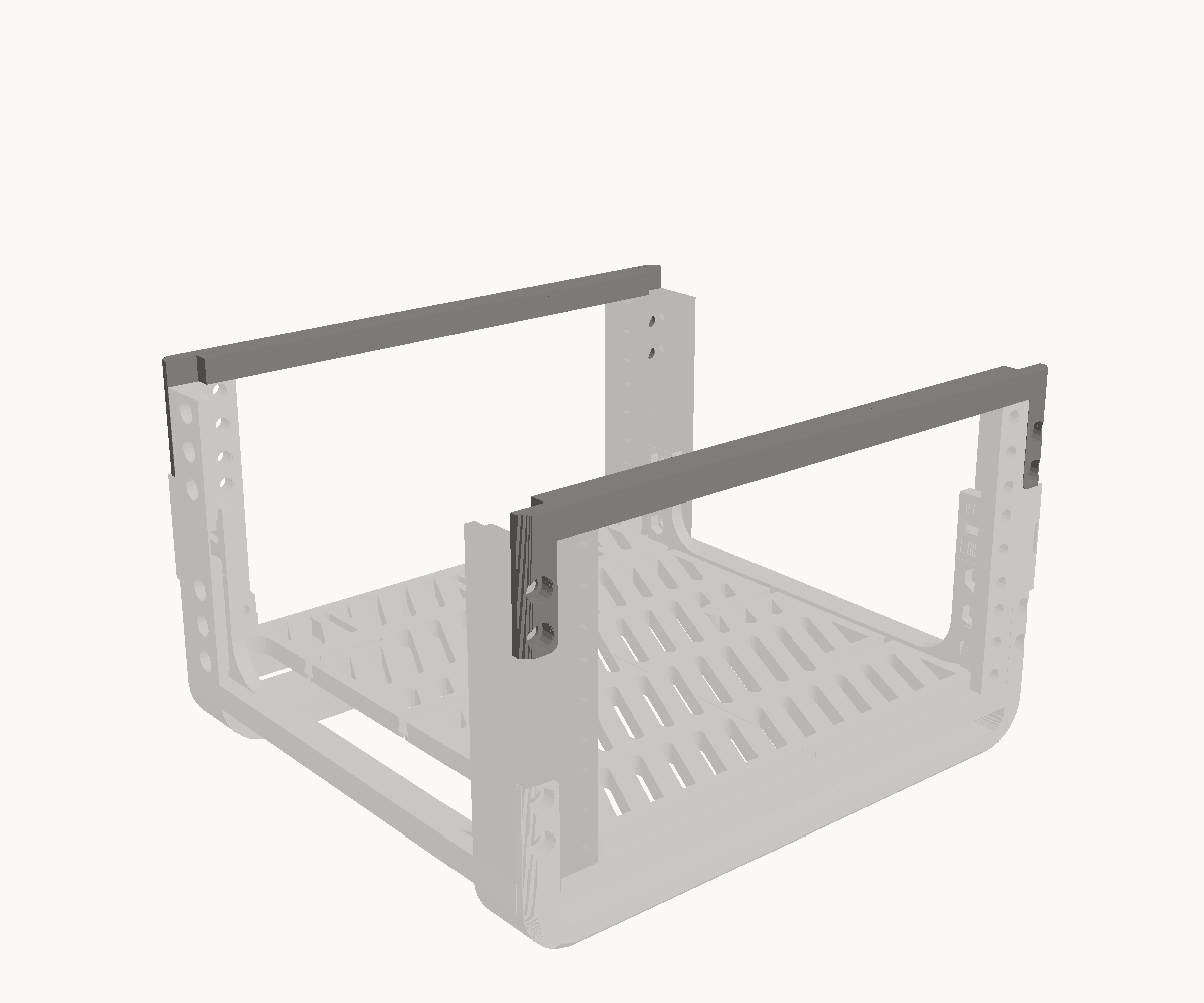
Step 4: Close the top with a bar at each end
- 2
- Top bar
- 8
- M6 x 16 socket screw
- 8
- M6 nyloc nut (DIN 985)
A top bar goes on the way a bottom bar did, the other way up: its spine lies across the posts’ tops and its ears hang down the faces into the top pockets, flush. Two M6 × 16 through each ear from the front, into a nut behind the mounting plate. One across the front, one across the back.
Check. Both spines down flat on the post tops, both pairs of ears flush with the faces. Three units: a post stands 133 mm from foot to top.
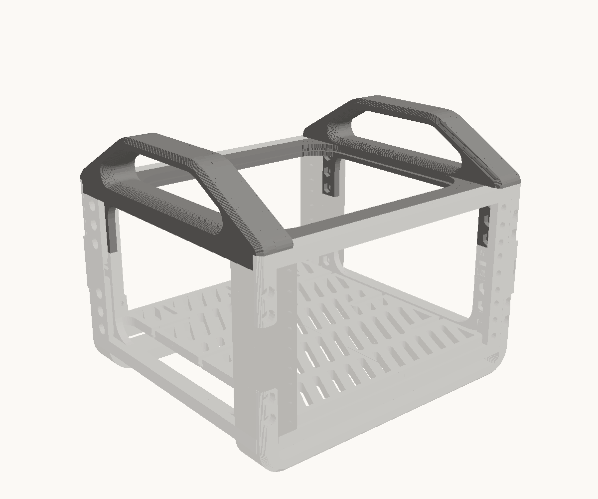
Step 5: Hang the two handle rails
- 2
- Top rail, handle
- 12
- M6 x 16 socket screw
- 12
- M6 nyloc nut (DIN 985)
One rail each side, hung from the top posts the way a side rail hangs at the bottom, upside down: the web inside the post’s side plate with its bores opening into the rack, the lid on the posts’ tops, the notch at each end over the top bar. Drop a nut into each of the three traps per end, then three M6 × 16 from outside through the side plate. The left rail is the right rail turned half round. A flat rail, if you asked for one instead, goes on exactly the same way; a rack ordered with nothing on top has no rails and is finished at the step before.
Check. The two rails’ arms meet at the centre line, front and back, and the top bars sit in their notches. Lift the rack by the handles and nothing shifts.
The 3U extension
12 printed parts, 40 bolts, 3 steps.
You need
- 5 mm hex key, for the M6 screws
- 10 mm spanner, for the nuts
In the box
| 4 | Post |
|---|---|
| 4 | Splice strap, front |
| 4 | Splice strap, side |
| 36 | M6 heat-set insert, 8 mm |
| 40 | M6 nyloc nut (DIN 985) |
| 40 | M6 x 16 socket screw |
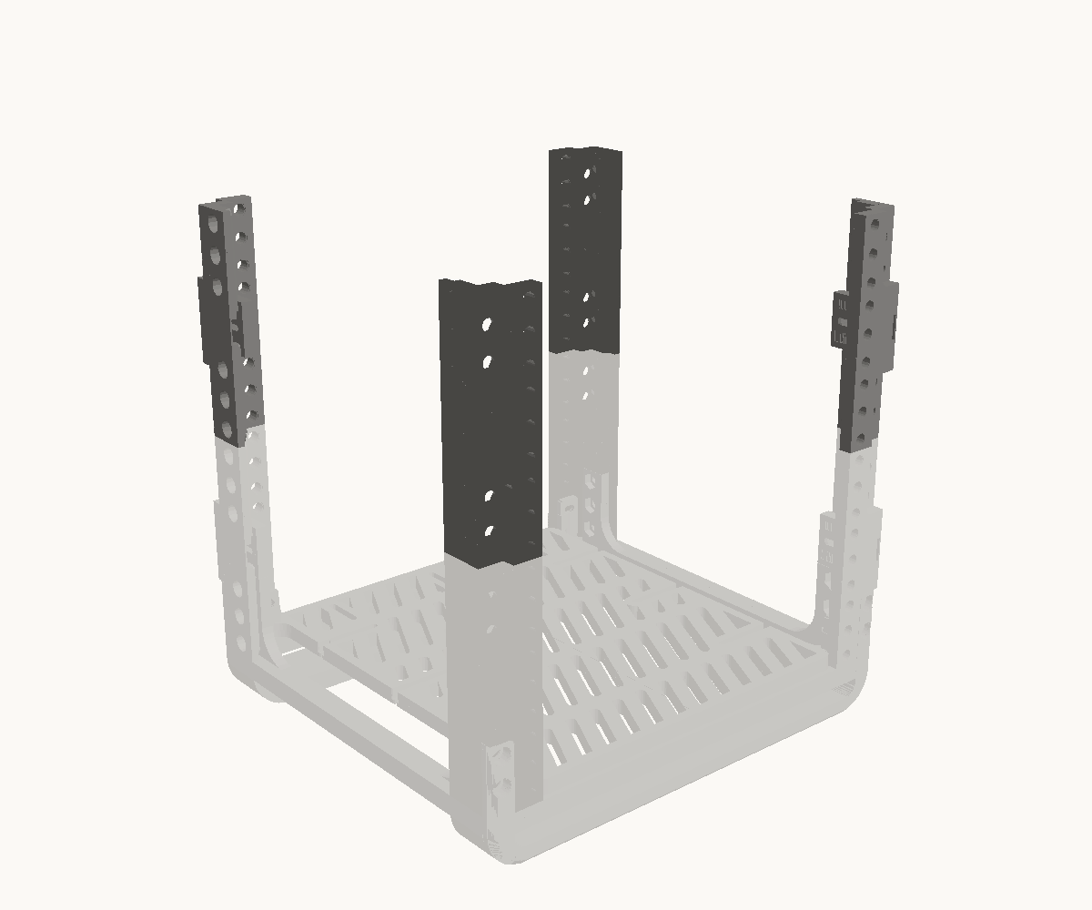
Step 1: Take the top bars off and stand a post on each post
- 4
- Post
The top bars come off first — eight bolts, kept with the bars — because a bar’s ears and a splice strap use the same pocket in a post’s end. Then stand a new post on each post below, end to end, mounting face the same way. Nothing fixes the two yet: the joint is the straps.
Check. Four posts standing on four, the hole columns running straight through the joint and the mounting faces flush.
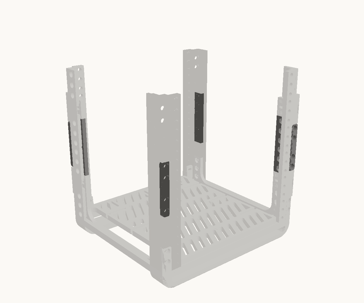
Step 2: Strap every corner, front and side
- 4
- Splice strap, front
- 4
- Splice strap, side
- 40
- M6 x 16 socket screw
- 40
- M6 nyloc nut (DIN 985)
The front strap sits in the two pockets that meet at the joint, flush with the face, its bores to the front: two M6 × 16 into each post, nuts behind the mounting plate. The side strap goes inside the side plates across the joint with its bores opening into the rack: drop a nut into each of its six, then three M6 × 16 into each post from outside.
Check. Every strap bears half on each post. Ten bolts per corner, forty in all, and the joint adds nothing to the height.
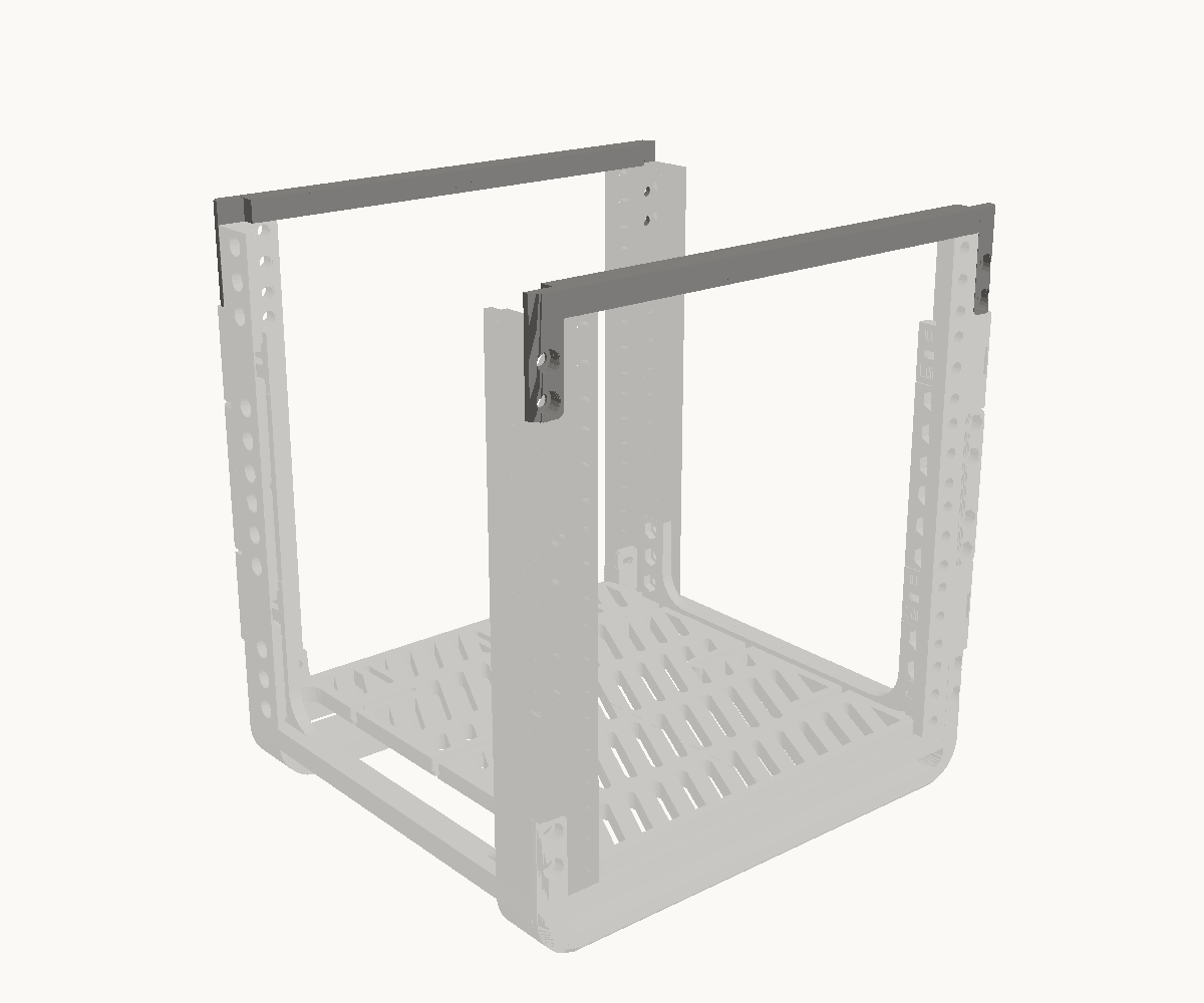
Step 3: Put the top bars back, on the new top
- 2
- Top bar, from the section below
The same eight bolts and the same pockets, one section up: spine across the posts’ tops, ears down the faces, flush. A flat top or handles moves up with them, its rails onto the new top posts’ side plates.
Check. The rack is 6U from foot to top, and nothing is left over but the box.
The 3U base kit
14 printed parts, 44 bolts, 5 steps.
You need
- 5 mm hex key, for the M6 screws
- 4 mm hex key, for the M5 screws
- 10 mm and 8 mm spanners, for the nuts
In the box
| 4 | Post |
|---|---|
| 2 | Bottom bar |
| 2 | Top bar |
| 2 | Side rail |
| 1 | Base tile, front |
| 1 | Base tile, back |
| 2 | Top rail, handle |
| 36 | M6 heat-set insert, 8 mm |
| 40 | M6 nyloc nut (DIN 985) |
| 40 | M6 x 16 socket screw |
| 4 | M5 x 20 socket screw |
| 4 | M5 nyloc nut (DIN 985) |
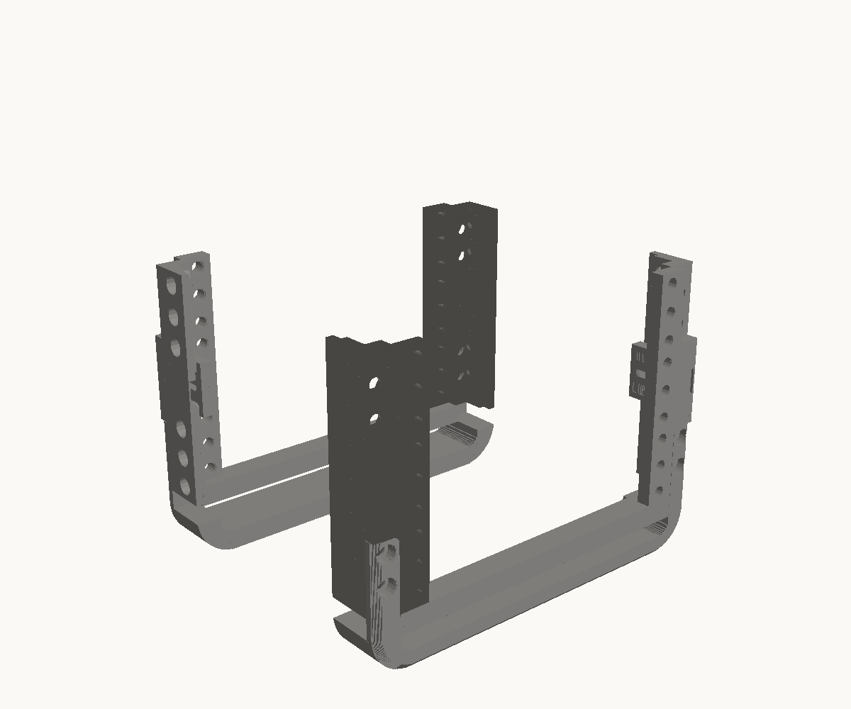
Step 1: Bolt a bottom bar across each pair of posts
- 2
- Bottom bar
- 4
- Post
- 8
- M6 x 16 socket screw
- 8
- M6 nyloc nut (DIN 985)
Stand two posts up with their mounting faces towards you and their side plates outward, and drop a bottom bar’s ears into the pockets at their feet, spine down: the ears sit in the pockets flush with the faces. Two M6 × 16 through each ear from the front, into a nut behind the post’s mounting plate. Make the second pair the same way; it becomes the back, turned round.
Check. Two U-frames. Ears flush with the faces, nothing standing proud, and the side plates on the outside of each.
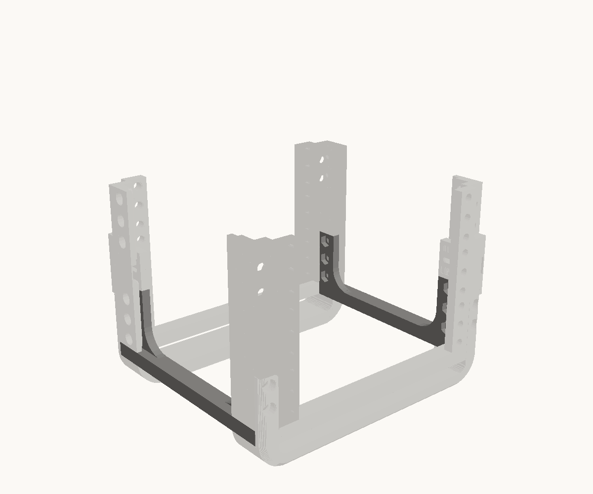
Step 2: Join the two with the side rails
- 2
- Side rail
- 12
- M6 x 16 socket screw
- 12
- M6 nyloc nut (DIN 985)
A side rail runs between a front post and a back post: its flange turned outward under the posts’ feet, and the bolt plate at each of its ends standing inside the post’s side plate. Drop a nut into each of the three traps in the plate from inside the rack, then three M6 × 16 through the side plate from outside, into them. The other rail the same on the other side.
Check. The rack stands square on its bars and rails. Each rail’s plate is inside the post’s side plate, not outside it, and three bolt heads show on the outside of every post’s foot.
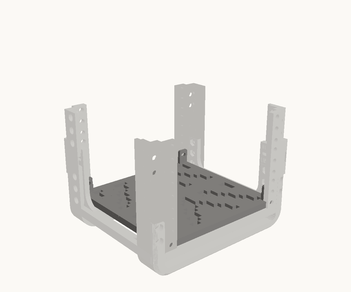
Step 3: Lay the base in and bolt it up into the posts
- 1
- Base tile, front
- 1
- Base tile, back
- 4
- M5 x 20 socket screw
- 4
- M5 nyloc nut (DIN 985)
Two tiles, each running the full width of the rack with a prong at each end, meeting across the middle where their edges lap. Each prong goes up inside a post behind its mounting plate; the front pair sit flat against the plate. Line the slot in each prong up with the post’s second mounting hole from the bottom and put an M5 × 20 through from the face, into a nut on the far side of the fin.
Check. All two tiles flat with their laps closed, the base on the same plane as the rack’s feet, 3 mm back from the front faces. A rack ordered with an open bottom has no tiles: skip this step.
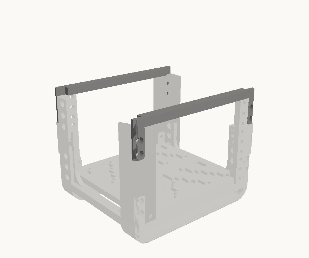
Step 4: Close the top with a bar at each end
- 2
- Top bar
- 8
- M6 x 16 socket screw
- 8
- M6 nyloc nut (DIN 985)
A top bar goes on the way a bottom bar did, the other way up: its spine lies across the posts’ tops and its ears hang down the faces into the top pockets, flush. Two M6 × 16 through each ear from the front, into a nut behind the mounting plate. One across the front, one across the back.
Check. Both spines down flat on the post tops, both pairs of ears flush with the faces. Three units: a post stands 133 mm from foot to top.
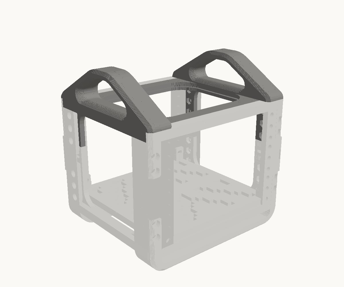
Step 5: Hang the two handle rails
- 2
- Top rail, handle
- 12
- M6 x 16 socket screw
- 12
- M6 nyloc nut (DIN 985)
One rail each side, hung from the top posts the way a side rail hangs at the bottom, upside down: the web inside the post’s side plate with its bores opening into the rack, the lid on the posts’ tops, the notch at each end over the top bar. Drop a nut into each of the three traps per end, then three M6 × 16 from outside through the side plate. The left rail is the right rail turned half round. A flat rail, if you asked for one instead, goes on exactly the same way; a rack ordered with nothing on top has no rails and is finished at the step before.
Check. The two rails’ arms meet at the centre line, front and back, and the top bars sit in their notches. Lift the rack by the handles and nothing shifts.
The 3U extension
12 printed parts, 40 bolts, 3 steps.
You need
- 5 mm hex key, for the M6 screws
- 10 mm spanner, for the nuts
In the box
| 4 | Post |
|---|---|
| 4 | Splice strap, front |
| 4 | Splice strap, side |
| 36 | M6 heat-set insert, 8 mm |
| 40 | M6 nyloc nut (DIN 985) |
| 40 | M6 x 16 socket screw |
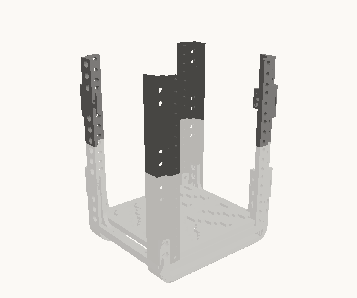
Step 1: Take the top bars off and stand a post on each post
- 4
- Post
The top bars come off first — eight bolts, kept with the bars — because a bar’s ears and a splice strap use the same pocket in a post’s end. Then stand a new post on each post below, end to end, mounting face the same way. Nothing fixes the two yet: the joint is the straps.
Check. Four posts standing on four, the hole columns running straight through the joint and the mounting faces flush.
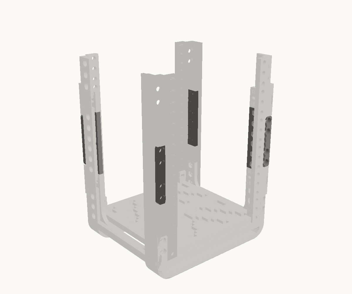
Step 2: Strap every corner, front and side
- 4
- Splice strap, front
- 4
- Splice strap, side
- 40
- M6 x 16 socket screw
- 40
- M6 nyloc nut (DIN 985)
The front strap sits in the two pockets that meet at the joint, flush with the face, its bores to the front: two M6 × 16 into each post, nuts behind the mounting plate. The side strap goes inside the side plates across the joint with its bores opening into the rack: drop a nut into each of its six, then three M6 × 16 into each post from outside.
Check. Every strap bears half on each post. Ten bolts per corner, forty in all, and the joint adds nothing to the height.
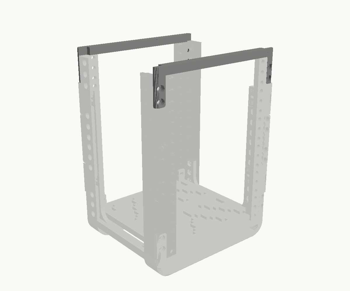
Step 3: Put the top bars back, on the new top
- 2
- Top bar, from the section below
The same eight bolts and the same pockets, one section up: spine across the posts’ tops, ears down the faces, flush. A flat top or handles moves up with them, its rails onto the new top posts’ side plates.
Check. The rack is 6U from foot to top, and nothing is left over but the box.